Introduction
Currently, Michigan Aeronautical Science Association (MASA) uses Ammonium Perchlorate Composite Propellant (APCP) pucks to ignite its RP-1/LOX Engines. These pucks are inherently dangerous to manufacture and have proven to only have about a 50% ignition reliability. The torch igniter project is meant to target these issues by creating a safer, reusable, and more reliable method for engine ignition.
Igniter Body
The igniter body was sized for lighting the MASA RP-D2 engine, which can produce a thrust of about 4080 lbf at a chamber pressure of 440 psi with a mass flow rate of 11.75 lb/s.
Mass Flow: After a thorough literature review, it was determined that the igniter needs to have a total mass flow of 0.5% of the engine’s mass flow to ensure main engine ignition. (NASA-SP-125, p. 140) With a 15% margin, this results in a total mass flow rate of 0.068 lb/s or 30.8 g/s.
Propellants: The propellants chosen are gaseous methane and gaseous oxygen. Methane was chosen due to its high ignitability (5-15.8% mol in air) while being safer to work with than other gasses such as hydrogen or acetylene.
Mixing Scheme: The igniter uses a direct impingement mixing scheme. Because the igniter uses gaseous propellants, a direct impingement scheme is sufficient and allows for easy manufacturing.
Material: The material used for the igniter body is 304 stainless steel. This material was chosen because of its corrosion resistance and oxygen compatibility.

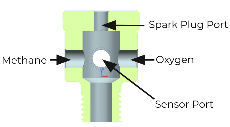
Below are the drafts of the igniter body and igniter top cap.
Feed System
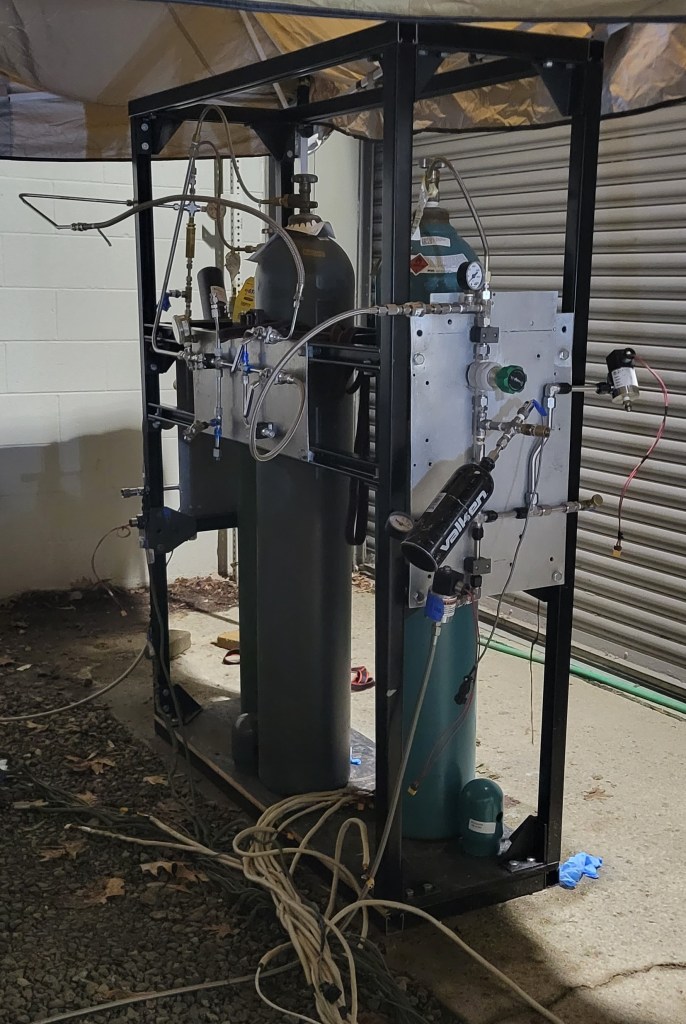
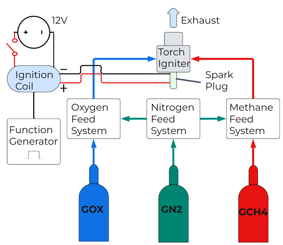
The feed system is comprised of 3 major subsystems: nitrogen, oxygen, and methane. The nitrogen system is connected to both of the propellant systems and is used for purging the systems, as well as for cold flow testing. The oxygen and methane systems are connected to the igniter through orifices and solenoids. Each system has solenoids, relief valves, check valves, gauges, and pressure transducers. Everything is mounted on a custom-made rack, designed to reduce clutter and streamline operations.
The systems were assembled with off-the-shelf components with everything being connected via 0.5 inch diameter tubing. The feed system assembly was done in-house. This includes tube bending, tube flaring, torquing fittings, leak checking, oxygen cleaning, etc.
Results
The igniter was first hydrostatically tested at 200 psi (safety factor of 2) to ensure that the welds will withstand operating pressure of 90 psi. Then, the igniter was put through multiple cold flows to ensure all feed systems and avionics were operating nominally. Finally, the team carried out a series of ten hot fires lasting 1.2 seconds each with varying O/F ratios. The igniter produced seven successful firings and three unstable ignitions, some of these tests can be viewed in the video at the top of the page.
The igniter reliability was calculated based on the following formula: r = 100×(1/N)×∑(Si), where r is the ignition reliability (%), N is the number of tests, and Si is the combustion stability (0 – no combustion, 0.5 – unstable, 1 – stable). Based on this metric, the igniter has an 85% reliability score, while the current MASA APCP igniter pucks have a reliability score of only 50%.
Limitations
The most notable limitation of this project is the lack of an integrated combustion chamber test. This would involve mounting the torch igniter and corresponding feed system inside a MASA combustion chamber, and determining if the igniter is capable of lighting said engine. The primary reason for not conducting this testing is the time-intensive nature of designing and fabricating an engine compatible with the torch igniter, given the project’s limited duration of 15 weeks.
The other limitation of this project is the lack of sensors on the systems and igniter. Unfortunately, the team did not have enough budget to integrate proper pressure transducers (PT) and thermal couples (TC). While the systems did include some PTs, they were not specifically sized for the systems and igniter, which meant they did not have a sufficient resolution and, therefore, did not give accurate data.
Future Work
The team recommends that the next steps should be the refinement of the feed system to include better pressure readings and less components. The igniter should also be integrated with a combustion chamber to test its ability to ignite an engine. This could involve retrofitting an igniter into an older MASA engine or designing and manufacturing a new engine that incorporates the igniter into its design. Finally, the igniter can be optimized to reduce mass for a flight-ready version.
